Solus-N Build Thread
    Solus:
      Adjective
      single; alone; unique

    Etymology so- + lés
      Adjective
      1.bright
      2.(of sound) clear
      3.(intellectually) clear, lucid

    {N - for Nitrous}
|

|
Design

Loaded
45 lbs
CG 80 inch
CP 117 inch
stability 10.5 caliber
|
|
Empty
27 lbs
CG 76 inch
CP 117 inch
stability 11.6 caliber
|
Motor
N-1000
10 second burn time
15 lbs N2O (approx)
2.5 lbs PVC fuel grain (approx)
*numbers are approximate
|
Tank and Combustion Chamber
The Nitrous tank, combustion chamber, and payload section are comprised of
3.25" OD by 3.00" ID 6061 Aluminum tube. There was nothing unusual about
cutting the aluminum tubes, with the possible exception of squaring the
ends. The ends of the tubes need to be close to square, but not perfect
since aluminum couplers and screws will be used to connect the parts.

Squaring the ends of the tubes
|
The tubes were squared by hand using a file, a flat plate, and 4
angles. Although this seems tedious the work progressed quickly and
required less than an hour to square 6 tube ends.
|

Polishing the tubes
|
Polishing the tubes, or as I like to call it.. one more example why
women live longer than men. This is a picture of a 66" tube on a lathe
half as large, with additional support provided by a steady rest clamped
to a drill press, and also supported by a JawStand.
|

Cleaning the Nitrous Tank
|
Cleaning the Nitrous tank with Acetone.
|
Nosecone
While making the nosecone, my wood lathe seized. When I removed the motor
and cracked open the motor case, ALL the dark sawdust, seen in the
foreground of this picture, fell out of the poor guy. The sawdust must
represent years of accumulation. I cannot imagine how the lathe worked at
all. In a typical Tim Allen style move, I bought a replacement motor with
MORE POWER. It didn't fit of course, but after an all-nighter
bending parts and removing some of the metal case, I was back in business.

Dead Motor from Wood Lathe


Fin Can
The rough shape of each fin is cut from sheet aluminum on a bandsaw. In
the future I must remember to cut the fin from interior aluminum only.
After the fin can was completed I noticed the factory cut edge of the
aluminum sheet was a little rough. The edge wasn't bad enough to warrant
remaking any of the parts.

Raw cutting the fin
Just like the old recommendation in the instructions in Estes kits, the
fins are clamped together and ground until they are identical. Grinding
the fins using a belt sander was simple, quick, and easy.

Grinding the fins to be identical

|
This is a photo after grinding one side of the fin.
The results are perfect!
|

|
Next a section of 3/4 x 3/4 x 1/8 aluminum angle is cut. One leg of the
angle is shorted by 1/2". Holes are drilled, the leading edge is angled,
and the fin and angle are screwed together.
|
The final step before mounting the fins to the fin can is polishing the
parts. A polishing wheel and red iron oxide is used. After polishing, the
fins have a surface almost as perfect as a bathroom mirror. Below are
before and after pictures.

Before and After Polishing
Next the fins are mounted to the fin can.
The radial location of the fin is determined using a piece of wrap-around
paper, a ruler, and a diamond glass cutter to mark the location on the
aluminum. Using magnifier glasses helps a bunch to get good measurements
and good markings. After the locations of the fins are marked on the fin
can, a protractor provides a quick sanity check.

Determining Radial Position of Fins
A fin mounting jig was cut from high quality furniture grade wood. This
fin mounting jig is so simple to make that I normally just throw-away the
jig when Im finished. The results are excellent. (I need to write a how-to
page for the fin mounting jig.. coming soon..)
The fins are mounted one at a time. I used JBWeld metal based epoxy to
attach the fins to the fin can. In tests I was able to put opposing fins
on blocks of wood and stand on the middle of the fin can without the part
bending or breaking. The aluminum angles provide a lot of surface
area for the metal based epoxy to grip. If this rocket were to exceed mach
2, I think a better attachment protocol would be needed, but this design
should work fine for Solus-N.
The radial position has been marked, the fin jig creates perpendicular
alignment, and then I use my Photoshop Alignment Method to make sure
everything is perfect before the JBWeld sets. The Photoshop Alignment
Method is described here.

Fin Can, Fin, and Fin Mounting Jig


The final results. Im pleased!
Injector and Bulkhead
The injector is a 5 port injector in a Urbanski-Colburn (UC)
configuration. Four of the five ports are plugged, and the remining port
doubles as a fill tube for the motor. At ignition, the plugs and Nylon
fill tube burn-though, allowing theNitrous to flow into the combustion
chamber. See the photos in the
Ignitor and Pre-heater
section for more details.

Injector 2 views

Chamber Pressure Sensor
The injector face and back plate were machined from stock 6061 aluminum.
The holes in the injector face were drilled on a lathe using a 4 jaw
independant chuck instead of a drill press so that perpendicular threads
could be started. Usually perpendicular threads can be cut using a tap in
the drill press chuck, but large NPT tapers require too much force for me
to turn by hand. The lathe chuck worked fine.

Drilling injector using 4 jaw independent chuck
|

Hand threading the injector face
|

Drilling the injector back plate
--The pressure sensor
Running a sensor tap through the injector to measure combustion chamber
pressure proved more difficult than I imagined. Several methods were tried
and failed before I settled on the hole in the screw pictured above. The
photo below shows one failed design where the injector explosively
disassembled when pressurized. The bolts failed in tension.

Injector failure under pressure
Parachute
Description here:
http://www.spiegl.org/rocket02/parachute
Electronics


Fuel Grain
The fuel grain is comprised primarily of gray Schedule 80 PVC pipe,
available from a plumbing supply house. The forward end of the PVC
contains 4 notches which align with the 4 stainless bolts on the face of
the ignitor. Red RTV is used to ensure an air tight seal against the
injector. The aft end of the grain is ground flat and red RTV is also used
to ensure a tight seal against the nozzle. Additional O-rings and
machining are not necessary when RTV is used.
Next, the PVC grain is wrapped in a sheet of EPDM rubber. The width of the
EPDM rubber is 1.25x the circumference of the PVC tube. In other words
the EPDM overlaps itself by 25%. The purpose of the EPDM is a) insulate
the case hardware from heat b) the web thickness of the PVC is very close
to a burn through. The EPDM provides just enough thickness to alleviate
the risk. c) make the fit between the fuel grain and the case hardware tight.
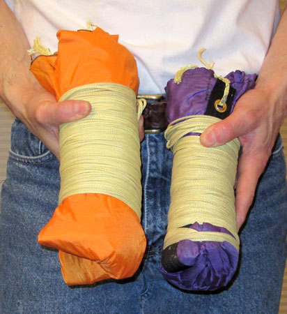
Finally, the PVC and EPDM are wrapped in brown craft paper. EPDM rubber
doesn't want to slide into aluminum. It sticks. The paper allows easy
motor prep.

Fuel grain expanded view

Fuel grain assembled view

Fuel grain with surrounding parts shown
Ignitor and Pre-heater
The ignitor and pre-heater are simplified solid rocket fuel grains
designed to provide significant heat and flame in order to a) open the UC
valves and b) light the hybrid rocket motor. The Nylon tubes and Nylon plugs
burn away releasing the pressurized Nitrous Oxide. The pressurized Nitrous
flows through the injectors, into the burning pre-heaters, and combustion
of the PVC solid grain commences. Even after the pre-heater extinguishes,
the Nitrous and PVC continue to burn.
Pre-heater formula
Ammonium Perchlorate 200u
Aluminum -325 mesh
HTBP
Dioctal Adipate
Isonate 143L
|
75%
1.75%
14%
7%
2.25%
|
Engineering the pre-heater was one of the most challenging parts of this
project. Various attempts, videos, and discussions appear elsewhere on this
web site. Below is a picture of the design which ultimately worked.

Segmented pre-heater expanded view

Segmented pre-heater assembled
Discussion of this design and video
here.
[UP]